Loading...
WebGPU Renderer: Meshes and Materials
02/13/2024
Controls
Overview
This is the third post in a series I am doing on creating my own renering engine using the WebGPU API. In this post I document the steps I took in order to get a functional Material and Mesh system working. You can see this in action in the interactive demo above.
Renderables
In this update, I've introduced a new type of object called a Renderable. A Renderable represents an object in a scene that will be rendered to the screen. It consists of two elements: a Mesh and a Material. The Mesh defines the faces, points, or lines that compose the shape of an object, while the Material determines how a mesh appears when viewed on the screen. Both Meshes and Materials are additional classes that have been added since the last update, and their implementation will be discussed in more detail later in this post. The benefit of having this Renderable class is that Renderables allow for an easy way to pair an object's shape with its appearance. With it, we can easily view the same geometry with different materials, or we can also see a single material used across many different geometries.
Materials
Another class I added is the Material class. The Material class holds all the information necessary for defining how a mesh will appear when rendered on the screen. Inside a Material object, the instructions for the vertex and fragment processing stages of the pipeline exist. These instructions are represented as code that can be executed on the GPU, known as 'shaders'. In webGPU, the language you write shaders in is called Web GPU Shading Language (WGSL). In this example, we see three different materials, each with their own shader code. A basic material that will render the object as a uniform color, a UV material that will render the object in accordance with each vertex's UV coordinate, and a normal material that will render the object in accordance with each vertex's normal vector.
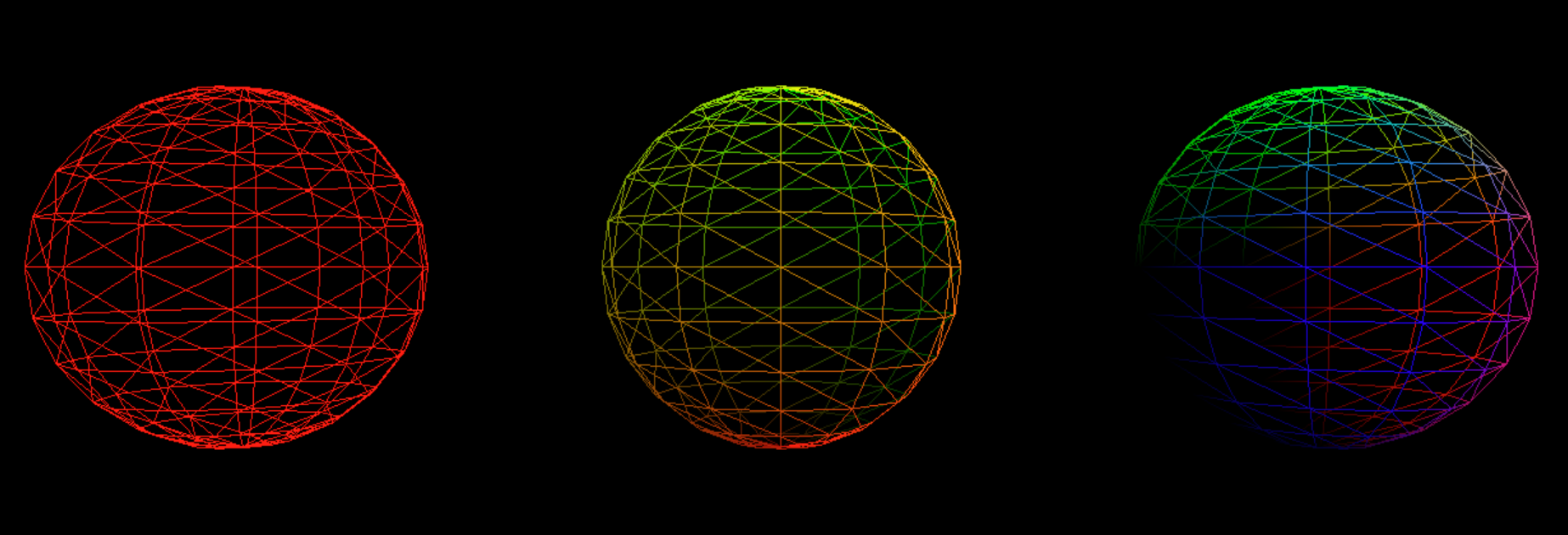 Here, we see the 3 materials on the same sphere mesh. From left to right: Basic, UV, Normal
Additionally, a Material object will also contain data buffers that are initialized on the CPU and sent to the GPU. Inside of these buffers will be data that can be used as variables inside of our shaders. These variables are known as 'uniform variables', as their value will remain constant for the entirety of the draw call. As an example, in the above scene, when 'basic' material is selected, each renderable's material has a buffer storing a color value which is sent to the GPU to render that object as that color.
Here, we see the 3 materials on the same sphere mesh. From left to right: Basic, UV, Normal
Additionally, a Material object will also contain data buffers that are initialized on the CPU and sent to the GPU. Inside of these buffers will be data that can be used as variables inside of our shaders. These variables are known as 'uniform variables', as their value will remain constant for the entirety of the draw call. As an example, in the above scene, when 'basic' material is selected, each renderable's material has a buffer storing a color value which is sent to the GPU to render that object as that color.
Lastly, a material object will store a description of how the rendering pipeline will function for this material. This allows us to configure how the material will look beyond just the shader code. For example, we can configure the pipeline to render line primitives rather than triangle primitives. This is how I am able to switch each material to wireframe mode.
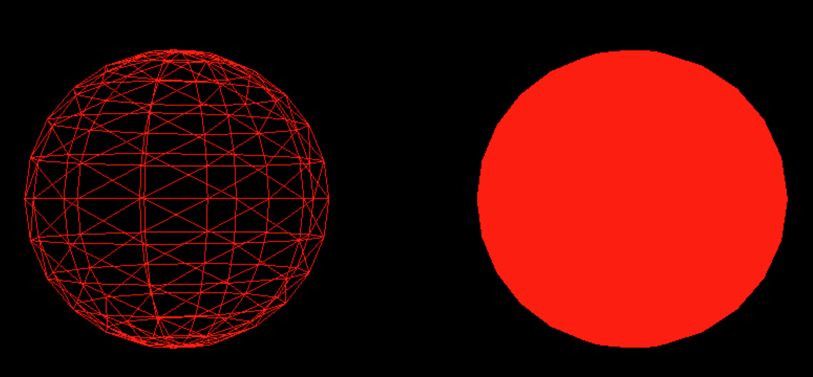 This image shows the same shader being used with two different pipelines. On the left, the pipeline renders line primitives, on the right triangle primitives
Meshes
The third class I implemented is the Mesh class. This class contains two buffers that will define the shape our renderable object will take. The first buffer stores data about the individual vertices of a mesh. Here, each vertex can have multiple pieces of data associated with it. To represent a wide array of geometry with my Mesh class, I have created several mesh sub-classes, such as Cube and Sphere, each with their own functions to generate values for these vertex properties. The first vertex property stored within this buffer is the vertex position, which is a float4 representing a homogeneous coordinate of the vertex's position in model space. For my mesh sub-classes, each class has a function that can generate a number of points based on a geometric function.
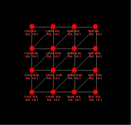 A visualization of position data for a plane mesh. The values on the x and y axis range from -0.5 to 0.5 to keep the center of plane at [0,0] while also maintaining side length of 1.
The next vertex property is their UV coordinate, a float2 that determines where a given vertex should sample a texture from, with values always ranging from 0 to 1.
A visualization of position data for a plane mesh. The values on the x and y axis range from -0.5 to 0.5 to keep the center of plane at [0,0] while also maintaining side length of 1.
The next vertex property is their UV coordinate, a float2 that determines where a given vertex should sample a texture from, with values always ranging from 0 to 1.
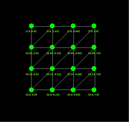 A visualization of uv data for a plane mesh. The values range of 0 to 1 in order to represent coordinates to be used in a texture lookup.
The last vertex property I store is the vertex normal, a float3 representing the normal vector for a given vertex, which will be useful later on once we begin to implement shading models.
A visualization of uv data for a plane mesh. The values range of 0 to 1 in order to represent coordinates to be used in a texture lookup.
The last vertex property I store is the vertex normal, a float3 representing the normal vector for a given vertex, which will be useful later on once we begin to implement shading models.
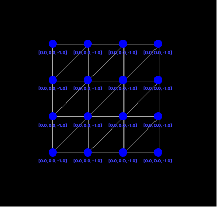 A visualization of normals data for a plane mesh. Here, every vertex has a value of [0,0,-1] as a plane is a flat surface, each normal will point in the same direction.
For more info on the math involved in creating some of these procedural meshes, check the links in the Resources section at the bottom of the page. Each vertex has all of its data stored consecutively within the buffer, and we give the GPU predetermined offsets so it knows how much data there is per vertex and how much data is required for each vertex property.
A visualization of normals data for a plane mesh. Here, every vertex has a value of [0,0,-1] as a plane is a flat surface, each normal will point in the same direction.
For more info on the math involved in creating some of these procedural meshes, check the links in the Resources section at the bottom of the page. Each vertex has all of its data stored consecutively within the buffer, and we give the GPU predetermined offsets so it knows how much data there is per vertex and how much data is required for each vertex property.
The second buffer the Mesh class holds will describe how vertices are connected with eachother to form the primitives that make up our mesh. If we want to render our mesh as a series of triangle primitives, we need to tell the GPU which three vertices make up a given triangle by providing it with a list of triplets, each consisting of indexes into our vertex buffer.
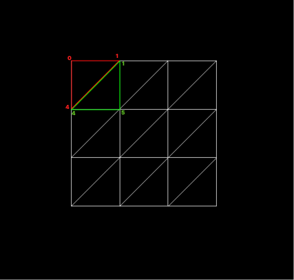 If we assume the vertices have been added into the vertex buffer from left to right, then top to bottom, we can see that the first triangle in red needs to use 0, 1, and 4th indices into the vertex buffer to form a triangle. The green needs to use the 1, 4, and 5th indices. This pattern will continue for all remaining triangles in the mesh.
If we want to render our primitive as a series of lines instead, like when viewing in wireframe mode, we give the GPU a list of pairs, each consisting of indices into the vertex buffer indicating where the line begins and ends.
If we assume the vertices have been added into the vertex buffer from left to right, then top to bottom, we can see that the first triangle in red needs to use 0, 1, and 4th indices into the vertex buffer to form a triangle. The green needs to use the 1, 4, and 5th indices. This pattern will continue for all remaining triangles in the mesh.
If we want to render our primitive as a series of lines instead, like when viewing in wireframe mode, we give the GPU a list of pairs, each consisting of indices into the vertex buffer indicating where the line begins and ends.
Resources
Real-Time Rendering 4th Edition - Tomas Akenine-Moller et al.
Procedural Sphere - Linden Reid
Procedural Torus - Linden Reid