Loading...
WebGPU Renderer: Lights
03/11/2024
Controls
Overview
This is the fifth post in a series I am doing on creating my own renering engine using the WebGPU API. In this post I document the steps I took in order to get a functional lighting system working. You can see this in action in the interactive demo above.
Lights
It is finally time to introduce light into our world. Light is such an important concept in rendering because, just as in the real world, it enables us to see things. Light flies through the sky, bounces off objects, and enters our eyes, allowing us to discern the shape and details of the objects that compose our world. This is what we aim to recreate in our rendering engine. Until now, the materials we have used to depict our objects have been statically colored, meaning they retain the same color and do not allow dynamic elements, such as lights, to alter their appearance. By introducing lights into our scenes and adjusting our shaders to utilize them, the pixels on our mesh surfaces can appear lighter or darker based on a lighting calculation.
If you imagine a sphere with our basic unshaded material applied to it, the image you would see in your head is that of just a plain circle. Its color is completely flat, with no variations. It lacks all dimensionality because it lacks shading. In fact, unless you had prior knowledge of the renderer, I would not blame you if you did not even know it was meant to be a 3D render! It is not until we add shading to our circle that it becomes clear to the viewer that this is a 3D sphere. If you've ever taken an intro art class or are the type to doodle on worksheets, you know the power that shading has to transform 2D into 3D.
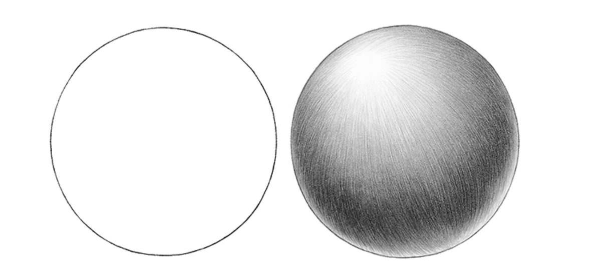 The circle on the left looks 2D because it lacks shading. Due to the shading on the circle on the right, our brain interprets the shape as 3D.
To achieve this effect in our rendering engine, we need to implement light sources (objects that emit light). There are three different types of light sources I want to implement into my engine, each with its own unique interactions with objects in the scene. These types are: Directional Lights, Point Lights, and Spot Lights.
The circle on the left looks 2D because it lacks shading. Due to the shading on the circle on the right, our brain interprets the shape as 3D.
To achieve this effect in our rendering engine, we need to implement light sources (objects that emit light). There are three different types of light sources I want to implement into my engine, each with its own unique interactions with objects in the scene. These types are: Directional Lights, Point Lights, and Spot Lights.
Sending Light Data to the GPU
Before we can start utilizing these lights in our shader code, we first need to send the necessary lighting data from our scene to our GPU. This includes things like a given light's intensity, color, direction, and a few other things that I will talk about later. This process of sending groups of data to the GPU is where I faced my first challenge of this chapter due to a slight quirk in how WebGPU operates.
My goal here is simple: to fill a memory buffer with chunks of memory, each chunk representing the variables associated with a given light. Then, inside the shader, all I have to do is define a struct with fields representative of the way the data chunk was filled, and then when the code runs, WebGPU will split the buffer into those struct-sized chunks for me, and everything will be good. For example, let's say a light object contains 3 fields: a vec3 for light direction, a float for light intensity, and a float4 for light color. If I define a struct in my shader as follows:
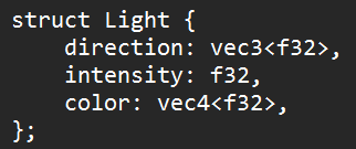 And say that my lighting storage buffer is an array of these structs, then every light in the storage buffer should be split up into this struct layout. That makes sense to me.
So I did this, and I began to notice something was not right. When trying to use these light values that I passed in, some of them were correct, such as the direction and the intensity, but some were just slightly off. If I passed in red as the color, the color might appear as blue, for example. For hours, this drove me crazy. I just could not figure out what was going on. This bug was sinister.
As it turns out, this was more of a knowledge gap bug rather than a 'me messing up my code' bug. After researching the topic, I found out that when passing data to the GPU, WebGPU expects your data to be aligned in a specific way. I found an extremely helpful resource called WebGPU Fundamentals (a link to the specific page is in the resources section) that goes into great detail on how these data alignment rules work. Not only that, but they also provide a tool where you can paste in your WGSL code, and it will provide a visualization of how your buffers should be aligned. Nice.
With this new knowledge in mind, I decided to create a general-purpose Light struct that would encompass all possible lighting variables for all light source types. Even though some of the fields of the struct would go unused for certain light source types, I felt as though this small data inefficiency would be worth avoiding further complication and headache of aligning more data structs. For reference, here is a visualization of my final Light struct's data alignment:
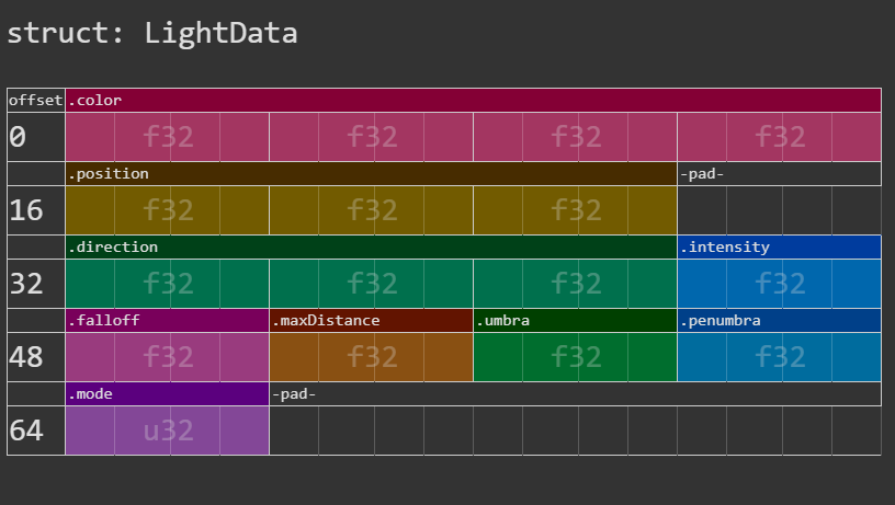 The layout of my Lighting Data struct I use in my shaders. Looking back on it, I see that the mode field could be squezzed in right after the position field. I'll have to remember to go back and fix that one day (cope).
Directional Light
The first, and simplest type of light source that I implemented, is the directional light. Directional lights have 3 parameters: direction, color, and intensity. Directional lights are considered the simplest type of light source because they do not have a position associated with them. This means that the light direction is constant for all objects in the scene. You can think of a directional light as being similar to the sun. The sun may change position in the sky throughout the day, but if you isolated one single moment in time, for that moment, every object you see is being lit from the same direction by the sun. If the sun is directly above you, all things you see are being lit by light rays that are coming directly downward (this is not 100% true, but from our human perspective, a lot of the time, it seems to be this way).
For any given point on an object, we can determine how "lit" it will be by a light ray if we know the following information: the object's normal vector at a given point (which we have) and the knowledge that there are no objects between the point and the light ray. Let's ignore the condition of the light ray being obscured by another object for now and only focus on the object's normals. By taking the cosine of the angle between the point's normal vector and the inverse of the light vector, we can determine a value representing how much of the original light energy is being reflected at that point. This is referred to as the diffuse reflection coefficient.
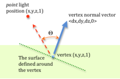 To find this value in our shader, it is as simple as taking the dot product of the normal vector and the inverse of the light vector (assuming both vectors are normalized). Then, with this value calculated (and clamped to 0 to remove any negative values), you can modulate the surface color at that point by that amount. For example, if this value ended up being .75, you could have the color of the surface at that point be its color multiplied by .75. This makes sense because if you imagine the case in which the value is 1, that would mean that the normal vector is pointing in the same direction as the inverse of the light direction. In this case, the maximum amount of light would be reflected, making that point the most "lit" by the light source. Conversely, if the value is less than or equal to 0, that would mean that the normal is facing away from the light, and no light could be reflected, making that point not "lit" at all.
Point Light
Point lights differ from directional lights in that, rather than having the light vector be constant for all points in the scene as is the case with directional lights, with point lights, the light vector is dependent on the point light's position in space in relation to the point we are measuring. The light vector is measured as the direction from the light's point in space to the point on the surface we are trying to illuminate. Additionally, with point lights, the color of the light is attenuated by the distance of this light vector, or in other words, the further away an object is from the light source, the dimmer the lighting will appear to be.
You can think of point lights as being torches. When you hold up a torch, everything around it in a certain radius will be lit up, but as you look off into the distance, objects will begin to become darker and darker, until at a certain point, they are not being affected at all by the light of the torch.
One possible formula for calculating this light attenuation is:
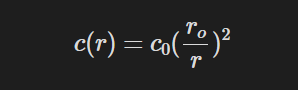 Here c_0 is the initial color of the light source and r is the distance from the position to the light source.
This is known as inverse-square light attenuation. While this gives generally good results, you can see that as the distance approaches 0, the attenuation value will get exponentially large, and if the distance is equal to 0, you will get a divide by 0 error. The way I accounted for this possibility is by adding a constant value to the denominator:
Here c_0 is the initial color of the light source and r is the distance from the position to the light source.
This is known as inverse-square light attenuation. While this gives generally good results, you can see that as the distance approaches 0, the attenuation value will get exponentially large, and if the distance is equal to 0, you will get a divide by 0 error. The way I accounted for this possibility is by adding a constant value to the denominator:
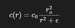 Here epsilon is some arbritary offset value. In my engine, I use 0.1
In addition to this problem that occurs when objects get too close to the light source, there exists an additional problem when objects get very far away from the light source. As our attenuation function stands, no matter how far away an object is from the light source, it is still technically being affected by the light, even if the light value is not perceptible at all. This adds performance overhead to our lighting system, which we want to limit. One solution to this problem, used by several game engines, is to multiply the attenuation function by a windowing function. This windowing function introduces a max distance beyond which all points will not be affected by this light source. The equation for that looks like:
Here epsilon is some arbritary offset value. In my engine, I use 0.1
In addition to this problem that occurs when objects get too close to the light source, there exists an additional problem when objects get very far away from the light source. As our attenuation function stands, no matter how far away an object is from the light source, it is still technically being affected by the light, even if the light value is not perceptible at all. This adds performance overhead to our lighting system, which we want to limit. One solution to this problem, used by several game engines, is to multiply the attenuation function by a windowing function. This windowing function introduces a max distance beyond which all points will not be affected by this light source. The equation for that looks like:
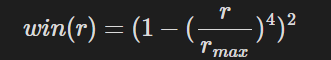 Here r_max is the maximum distance from the light source that we want to be affected by the light source.
Spot Light
Spot lights take the distance attenuation from point lights and add an extra dimension to it: directional attenuation. So, not only do objects that are farther away from the light appear dimmer, but objects that have a large angle between them and the light's direction will also appear dimmer.
You can think of spot lights as flashlights. Flashlights only have a certain distance in which they can illuminate, so objects that are closer to the flashlight will appear brighter. Along with this, objects that are in the direction the flashlight is pointing will be brighter than objects that are not in the direction in which the flashlight is pointing, even if they are the same distance away.
To calculate directional attenuation for spotlights, we need two additional light parameters: umbra, which is the maximum angle at which an object can still receive light from the spotlights, and penumbra, which is the maximum angle at which an object will receive full light intensity from the spotlight.
The functions for calculating directional attenuation is as follows:
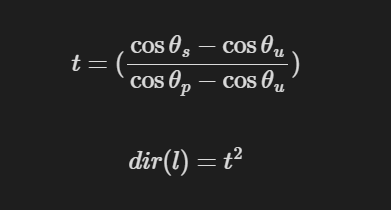 Here theta_s is the angle between the forward vector of the spotlight and vector from the light source to the point. Theta_u is the umbra angle. Theta_p is the penumbra angle
Gizmos
Because lights have no physical shape in our rendered scenes, it can be kind of hard to visualize what they are doing/where they are in your scene and what objects they are illuminating. This problem is only accentuated by the fact that I am determining their position and direction through JavaScript code rather than an interactive visual editor such as Unity. Because of this, I created some light gizmos to help visualize light positions and their respective lighting attenuations.
Resources
Real-Time Rendering 4th Edition - Tomas Akenine-Moller et al.
Memory Layout - WebGPU Fundamentals
WGSL Offset Computer - WebGPU Fundamentals
Seeing Light and Shadows - Create Your Art Out
Diffuse Lighting - Learn WebGL
Rat Model - Lillya